A Groundbreaking Platform for High-Resolution Solar Observations. Summary of its unique design and observational capabilities.
Abstract
The Dutch Open Telescope (DOT), located at the Observatorio Roque de los Muchachos (ORM) on La Palma, Canary Islands, stands out as a revolutionary solar telescope designed for high-resolution, large-field imaging of the Sun. By utilizing a completely open structure, both for its tower and the telescope, DOT minimizes thermal and atmospheric disturbances, allowing continuous high-quality observations of dynamic solar phenomena. The articles [Unique design of the Dutch Open Telescope, 2024] provides an in-depth overview of the telescope’s unique engineering design, optical configuration, and its contribution to solar physics, particularly in multi-wavelength observations of the solar atmosphere. Here’s a summary of the essentials.
Introduction
In solar astronomy, achieving high-resolution observations is crucial for understanding the dynamic processes in the Sun’s atmosphere. The challenge, however, lies in local earth atmospheric turbulence and thermal effects that degrade the quality of solar images, especially in traditional enclosed telescopes. The Dutch Open Telescope (DOT) overcomes these challenges through its innovative open structure, enabling unprecedented image stability and sharpness. The purpose of this article is to detail the design and operational principles of DOT, emphasizing how its open construction has advanced solar observation techniques and contributed to new discoveries in solar physics.
Engineering Design of the DOT
The DOT’s design is optimized for stable, high-resolution solar imaging, particularly under windy conditions. Its open-tower structure minimizes local atmospheric interference and eliminates heat buildup, a significant improvement over traditional enclosed designs.
Open Tower Design: Minimizing Atmospheric Turbulence
The DOT’s tower is a 15-meter-high open steel frame, designed specifically to allow wind to pass freely around the telescope, thus preventing the buildup of warm air that can degrade image quality. The idea of an open-frame tower emerged from extensive site-testing, where wind patterns were analyzed at different heights to minimize turbulence. The optimal height of 15 meters was chosen, as it provided the best balance between minimizing ground-level heat effects and maintaining stability in wind as shown in Figure 1 and Figure 2. More in formation in [Unique design of the Dutch Open Telescope, 2024] section 1. The open tower.
Figure 1: The open tower principle which followed from the site test measurements of Kees Zwaan. Left: Conceptual scheme. Right: Design scheme with open-foldable dome and telescope in parked position. Measurements with masts up to 30m height showed the mixing effect of wind. Large improvement of the seeing was in the height path from 10 to 15m. So a height of 15m was chosen for the open tower.
The design uses isosceles triangle geometry in the tower’s construction to enhance tilt stability. This allows the platform to remain parallel to the ground, even when the tower is subjected to wind gusts up to 20 m/s. The geometry prevents rotational instability, crucial for maintaining the pointing accuracy of 0.1 arcseconds necessary for solar observations. The way to the geometry of the open tower is explained in Figure 3.
Figure 2. The DOT on its open steel framework tower with a height of 15m. The left picture shows the enclosure open while the DOT is observing. The right picture shows the enclosure closed as protection against bad weather.
Figure 3. The way to the design of open tower with high tilt stability of the platform in gusty wind: a. Classical framework. This construction is very stiff against translations of the platform, however it turned out to be not stiff enough against rotations of the platform without using a big quantity of iron. b. Platform on posts. The platform remains parallel to the ground if the posts bend sideward under a wind load. However, this construction is not stiff against rotations about the vertical axis. c. 4-triangle truss with small platform and small base. Small triangle top angles are not stiff enough. d. 4-triangle truss with large base and large platform. Top angles of 30º give enough stiffness, however larger platform then corresponding to the size of the telescope mount. e. The 4 triangles shifted to the size of the telescope mount. Additional advantage is decoupling of the forces to ground of the feet of the perpendicular triangles giving less influence of ground deformation. f. Interferometer to measure platform tilt. L = Laser. B = Beamsplitter. Dots are small reflecting mirrors. I = Interference pattern of fringes, where an electronic counting system is placed to measure the shifts of the fringes.
Stability and Vibration Control
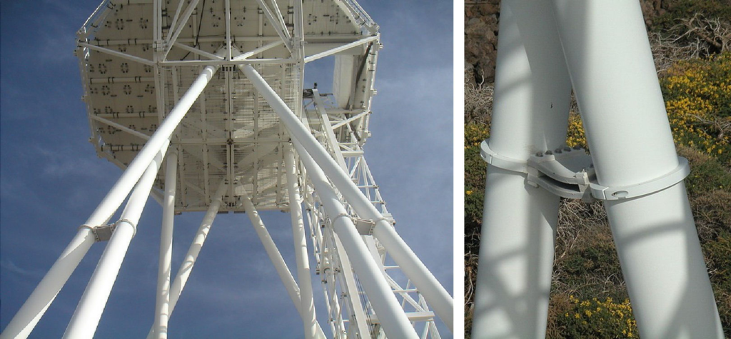
Wind-induced vibrations can significantly impact the stability of telescopes. The DOT tower mitigates this problem using dampers between the upward support tubes at mid-height, as shown in Figure 4, which effectively prevent resonance oscillations. The mechanical resonance frequency of the tower upward tubes is calculated to be around 5.8 Hz, with the wind velocity for vortex oscillations around 7.1 m/s. This combination of isosceles triangles and dampers ensures that the telescope structure remains stable during observations, even in gusty conditions, as shown in Figure 5, measurement b.
Figure 4. Vibrations caused by wind, known as Vortex Oscillations, are reliable prevented with dampers between the tubes. The photos in Figure 2 show the dampers, where two tubes pass closely to each other at half tower height. The dampers are here shown in more detail from nearby. Left: The dampers seen from the base of the tower. The damper on the right is near the ladder. Right: Damper in close up seen from the ladder. Two flexible rubber plates connect the tubes.
Figure 5. Measurements with the interferometer sensitive to tilt of the tower platform. The interferometer light paths are drawn in the tower scheme shown in Figure 3f at bottom right. Top a. Without wind and shining sun, then the warmer air near the ground comes upward and produces seeing bubbles. A bubble of some meters and a few degrees explains this bubble. Bottom b. The seeing bubbles disappear with wind of 2m/s or more. A wind gust of 9m/s gives no vibration and tilt change less than 0.1″. More information is in [Unique design of the Dutch Open Telescope, 2024], section 1, with explanation of the interferometer setup in particular in Figure 9.
Optical System Design
The DOT’s optical system is designed to maximize resolution and contrast by avoiding the thermal and optical distortions typical in enclosed telescopes.
Open Beam Design: Minimizing Temperature Gradients
One of DOT’s most significant innovations is its open primary beam design, where the air in the telescope’s beam is not enclosed, preventing it from heating up and disturbing the light path. Temperature differences as small as 0.1°C can reduce image sharpness due to refractive index variations in air. By keeping the beam open and the telescope structure exposed to ambient air, the DOT minimizes these temperature differentials, as explained in Figure 6.
Figure 6. Open telescope principle for sharpest images with explanation how it works. The index of refraction of air depends on the temperature. Temperature differences of 0.1°C within an imaging beam already start to reduce image sharpness. Large diameter beams can easier have such temperature differences of the air within the beam. The incoming air can be very homogeneous in temperature at the location of the DOT in the case of wind in the directions around the North direction from East to West. Without wind during the day with sun shining, the warm air bubbles from the ground dominate and sharp images are not possible. However, already wind from 1.5m/sec (5 km/h), more sure from 2m/sec (7km/h), improves the situation if the telescope is on an open tower, which prevents warm air bubbles coming upward from the ground and the walls of a building. The favorable situation can occur with changing temperature during the day. Measurements showed that even with temperature changes of the incoming wind air of 3°C in 15minutes, the required homogeneity of the air remains. With 2m/sec wind, 1800m air passes in 15 minutes (15x60x2=1800). For a temperature change of 0.1°C, there passes 60m air (1800/30=60). However, the telescope structure can not follow such temperature changes and will have a temperature deviating from the temperature of the incoming air. The air is to short nearby surfaces with deviating temperature, when the air can move with the wind through the primary beam free enough. Experiences showed that 80 percent open works. The low thermal conductivity of air is an advantage. However, it remains essential that the telescope structure has no places were stagnant air remains longer time and can take over the temperature of the structure surface.
The primary mirror, with a diameter of 45 cm, delivers diffraction-limited resolution, allowing sharp imaging across the visible spectrum. Despite its modest size, the mirror provides exceptional image quality, producing diffraction-limited images with a resolution of 0.2 arcseconds at 396.8 nm, in the violet Ca II H spectral line. Designs for larger mirrors of up to 140 cm and 250 cm are planned, which will further enhance the telescope’s capabilities. The construction to a larger mirror is shown in Figure 7.
Figure 7. DOT upgrade to a much larger mirror. a. Remove the existing telescope top, the mount is shown in the same position as in Figure 5. b. Place the new mirror with support on the existing equatorial mount, add a new telescope top, relocate the existing multi-channel imaging system to its side, and add new prime-focus optics. c. The result in observing position on top of the existing tower. The design for the 140cm diameter mirror fits inside the existing dome. The design for the 250cm mirror fits to a dome of 9m diameter equal to the GREGOR dome, which is built after the example of the DOT dome. The existing tower platform can support the 9m dome with some expansion.
Optical Path and Image Quality
The DOT’s optical path is kept simple to reduce stray light and maintain image contrast. After the primary mirror focuses the sunlight, the light is directed through a diaphragm plate, which selects a small part of the solar image to be processed. The diaphragm is cooled with a water circulation system, ensuring that heat from the intense sunlight does not affect image quality. Telescope with primary image on the diaphragm is shown in Figure 8.
Figure 8. The open telescope construction with the primary mirror on the left. The primary image of the sun is visible at the right as bright spot on the water-cooled diaphragm, which selects of the solar image a small part going through a hole in the diaphragm plate to the secondary optics.
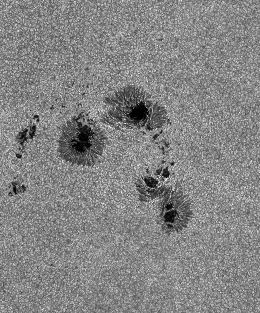
Additionally, the optical system uses secondary optics consisting of two doublet lenses that magnify the solar image by a factor of 10. These lenses correct for aberrations, allowing the DOT to achieve sharpness across a field of 4 arcminutes on the Sun, corresponding to a 24-mm image behind the lenses. This optical precision is essential for capturing fine details in solar phenomena like sunspots, granulation and solar flares as shown in Figure 9, 10 and 11. More information about the optical construction is in [Multi-wavelength imaging system for the Dutch Open Telescope, 2003] and about the reached capabilities for observations in [Advanced capabilities of the Dutch Open Telescope, 2013]. For more examples of images see Future and Images.
Figure 9. High resolution image of a piece of the Sun’s surface in the low photosphere in G-Band. Sunspot, the magnetic field is so strong that the gas flow outside is slowed down, making it cooler. Granules of the convection, bright rising gas in the middle, dark descending gas on the edges. Bright Points, fine clear serpentine structures in the dark lanes between the granules. Piece of field with Bright Points in the upper right frame is shown enlarged lower right. Scale in arc seconds.
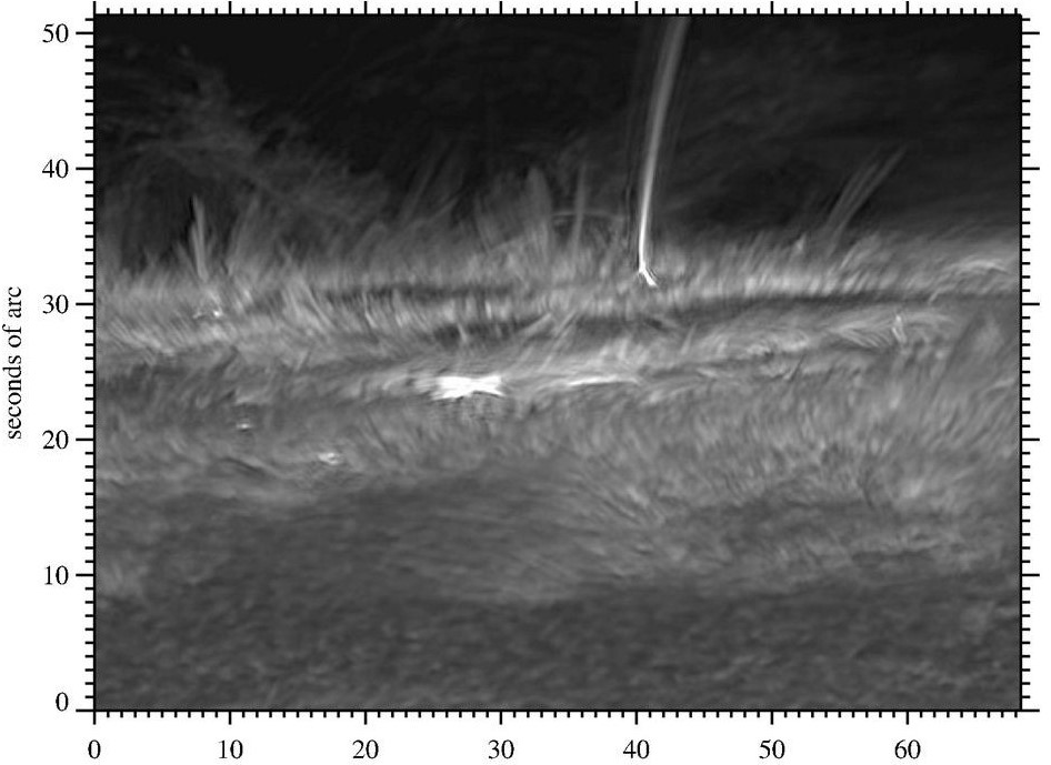
Figure 10. Sun edge with the fibrils, gas flowing outwards along magnetic field tubes.
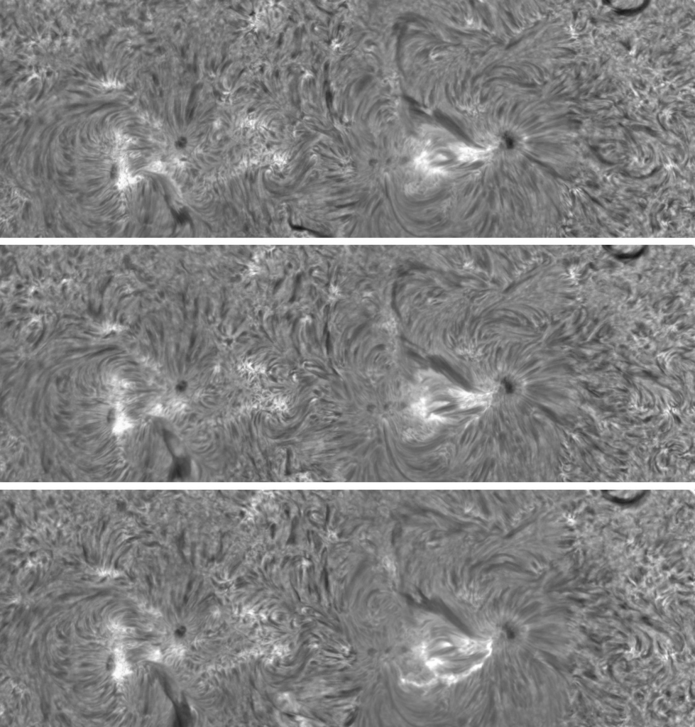
Figure 11. Three images from a mosaic movie over 5.5 hours with area of 2×6 camera fields. The size of the area is 480×165 arc-sec. The shown images are in the H-alpha line center at 656.3nm. A solar flare occurred 4.7 hours after the start of the observations. The upper two images are short time before the flare: 13.2 and 6.6 minutes. The bottom image is at the moment of the flare. A new active region is on the left side, an old one at the right side with magnetic boundary in between. New magnetic flux is welling up with high velocities in the new active region visible by the rapid change of the fibrils along the magnetic field. The interactions of the new and pre-existing magnetic fields can produce flares by de-stabilization of filaments, which are longer-lived bows of moving gas along the magnetic fields. The new bright structure seen only in the bottom image is a solar flare, first indication in its early stage in the middle image. The flare is from the old spot in the old active region in the direction of the new active region to the left side. The contrast of the structure in the field around the flare is seemingly lower in the bottom mosaic than in the two previous ones. This is because the program to represent the mosaic on the screen has an automatic contrast adaption to be able to clearly show the full range of intensities in the image especially during a solar flare. More information in [Advanced capabilities of the Dutch Open Telescope, 2013] about these images and in [Large-field high-resolution mosaic movies, 2013] also about how the mosaic movies are made.
Observational Capabilities and Achievements
Continuous High-Resolution Imaging
One of DOT’s most notable capabilities is its ability to capture continuous high-resolution movies of solar activity. The open design, combined with the high mechanical stability of the tower, allows the DOT to produce sharp, stable images for several hours, an achievement unmatched by most other solar telescopes. This ability to observe over extended periods provides critical data for studying solar dynamics such as the evolution of sunspots, granulation patterns, and magnetic field structures. [Manual for viewing DOT solar movies and papers with examples, 2013] tells you how to reach and play the movies of the observed images including many examples with explanations. The DOT is able to make movies also of mosaic images. The observation process for the intake of mosaics fast after each other is automated. [Large-field high-resolution mosaic movies, 2013] describes the developed technical process including a few examples.
Multi-Wavelength Observations
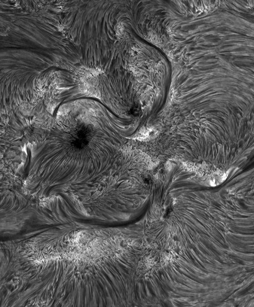
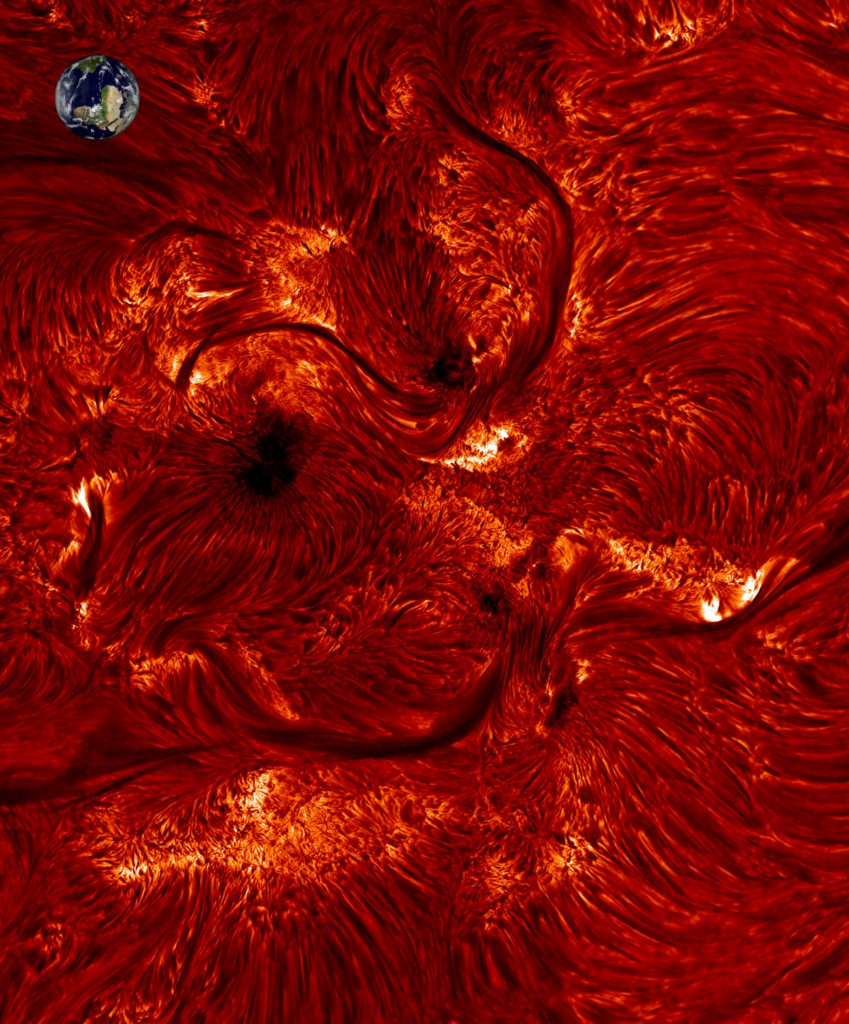
The DOT is equipped with a multi-channel imaging system that can simultaneously observe the Sun in seven different wavelengths. This capability allows for the tomography of the solar atmosphere, where layers at different heights can be observed using different spectral lines. For instance, the H-alpha line (656.3 nm) reveals structures in the higher chromosphere with the gas streams along the magnetic fields, while the Ca II H line (396.8 nm) provides insight into the lower chromosphere and the G-band (430.5 nm) the photosphere near the solar surface with the sunspots and bright points, both with upward magnetic field. Figures 12a, b and c show simultaneous made mosaic images in these 3 spectral lines, going upward from solar surface, where the magnetic activity comes up: Figure 12a G-band, Figure 12b Ca II H line and Figure 12c H-alpha line. Comparisons of these images are shown by shifting a line over the combined images in the website part Images. These combined images are the images here below 90° rotated to the left. Figure 12d is the same image as Figure 12c but colored afterwards to show better the regions with different brightness. An image of the Earth has been included to scale to show the large sizes of the structures on the Sun.
Figure 12a. G-band 430.5nm, filter width 1.0nm. Multitude of CH spectral lines shows the solar photosphere, the “surface” where the visible light with continuous spectrum escapes. Outside the active regions, the G-band shows granulation, the pattern of greyish blobs surrounded by dark inter-granular lanes. This granulation is the solar surface manifestation of the convection by which the sun transports energy through its outer part. The G-band also shows, with special emphasis, magnetic elements appearing as tiny bright structures, known as “Bright Points”. They cluster in the inter-granular lanes, being swept into these by the convective motions. They consist of slender, near-vertical magnetic “flux tubes” with magnetic field strength of about 1200-1500 Gauss. It takes a sharp telescope as the DOT to properly image these flux tubes. They brighten especially in the G-band because the CH molecules dissociate within the flux tubes, making these more transparent viewing pipes into the hotter solar sub-surface gas. The image can be enlarged on the screen for better visibility of the tiny bright structures. More information about the Bright Points and their influence on the higher solar atmosphere with DOT observations is in [DOT tomography of the solar atmosphere I to VII]. The motions of the bright points are studied in [Motions of isolated G-band bright points in the solar photosphere, 2003].
[Tunable H-alpha Lyot filter with advanced servo system and image processing: instrument design and new scientific results with the Dutch Open Telescope, 2006] describes the developed multi-channel system including the H-alpha filter, fast tunable through the spectral line to measure the gas-stream velocities away and towards the solar surface. Examples of movies with velocities observations are described in [Manual for viewing DOT solar movies and papers with examples, 2013] section 3, Velocity measurements from the images, with links to reach the movies.
Figure 12b. Ca II H line 396.85nm, filter width 0.13nm. Same solar area as G-band in Figure12a at exactly same moment. The Ca II H line is formed a few hundred kilometers above the solar “surface” as seen in white light and G-band. This is the low chromosphere at height of about 400km, precise height depends on the degree of activity. This line is due to once-ionized calcium and is one of the two strongest in the visible-light part of the solar spectrum. The other is its companion, the Ca II K line at 393.37nm. They are wide adjacent absorption lines in the violet part of the spectrum. At this height, the magnetic regions, where large numbers of magnetic elements cluster together, known as “plages”, are very bright, see [DOT tomography of the solar atmosphere IV. Magnetic patches in internetwork areas, 2005]. The dark areas contain “reversed granulation” with a partial contrast reversal of the granulation seen in the corresponding G band image in Figure 12a, see also the comparison images in the website part Images. Scientific explanation of the reversed granulation is in [DOT tomography of the solar atmosphere III. Observations and simulations of reversed granulation, 2005]. Some isolated small bright features in the dark areas are due to shocks in the solar atmosphere, made by low-frequency sound waves that travel upward and steepen into shocks where the gas density decreases at larger height, see [DOT Tomography of the Solar Atmosphere VII. Chromospheric Response to Acoustic Events, 2008].
Figure 12c. H-alpha line 656.28nm, filter width 0.025nm. Same solar area as G-band and Ca II H in Figures 12a and 12b at exactly same moment. Hydrogen H is about 80% of the solar gas and the H-alpha line is formed in the high Chromosphere about 2000km above the solar “surface”, again precise height depends on the degree of activity. The sunspot center parts with strong upward magnetic field, the umbrae’s, remain dark in H-alpha. Many so-called fibrils emanate away from the sunspots. They outline magnetic connections between different areas, like iron filings around a bar magnet show the magnetic field structure. The many fibrils show how complex solar magnetism is arranged within the solar atmosphere. The whitish areas surrounding the sunspots are plage, where large numbers of magnetic elements cluster together. The long slender dark structures are active region filaments. They end in bipolar regions where both positive and negative magnetic fields emerge through the solar surface. More, including instrument, see [Tunable H-alpha Lyot filter with advanced servo system and image processing: instrument design and new scientific results with the Dutch Open Telescope, 2006] and [DOT tomography of the solar atmosphere I. Telescope summary and program definition, 2004].
Figure 12d. H-alpha line 656.28nm, filter width 0.025nm. Image of Figure 12c with added colouring for more noticeable visibility of the structures. The inserted Earth photograph from space indicates the scale. The whole sun has a diameter of 109 times the earth.
By studying these layers simultaneously, solar physicists can gain a comprehensive view of processes such as magnetic reconnection, plasma flows, and energy transfer in the Sun’s atmosphere. The multi-channel system is crucial for studying the Sun’s atmosphere in three dimensions, offering valuable insights into how solar phenomena propagate from the photosphere to the corona. The references [DOT tomography of the solar atmosphere I to VII] are scientific papers focused on solar physics results with the tomographic multi-channel observations made by the DOT.
Scientific Contributions and Impact
The DOT has made significant contributions to solar physics, particularly in studying the fine structures of the solar atmosphere. Its high-resolution movies have revealed intricate details of sunspot umbrae and penumbrae, the fine-scale structure of chromospheric fibrils, and the dynamic behavior of solar prominences. One of the DOT’s unique contributions is the ability to observe solar phenomena in the late afternoon, a time when most other telescopes suffer from thermal distortions. The DOT’s open construction ensures that image quality remains high even during these periods, allowing for the study of solar activity at times when the Sun is low near the horizon. Example is the movie M01 in [Manual for viewing DOT solar movies and papers with examples, 2013], and shown here below. Figure 10 shows an image part from this movie, the part with the sun rim rotated upward.
In addition, the DOT has provided data that has been used to develop solar atmospheric models and improve our understanding of the interactions between the Sun’s magnetic fields and plasma, see the references [DOT tomography of the solar atmosphere I to VII] and [Motions of isolated G-band bright points in the solar photosphere, 2003] and many other papers, which can be found in the website part Publications.
The telescope has also played a critical role in advancing speckle imaging techniques, which allow for the reconstruction of high-resolution images from sequences of short-exposure frames, as explained in the paper of [DOT tomography of the solar atmosphere I. Telescope summary and program definition, 2004], section 5 Speckle acquisition and reconstruction.
Future Developments
The success of the DOT has spurred plans for further upgrades. There are proposals to install larger primary mirrors, potentially up to 250 cm in diameter, which would significantly enhance the telescope’s light-gathering power and resolution, see Figure 7.
Figure 13. Design for the European Solar Telescope (EST) with a 4.2-m diameter primary mirror. The dome is folded together in a ring shape below the platform and, consequently, the telescope is completely above the open dome. The semi-transparent windshield, see [The GREGOR dome, pathfinder for the EST dome, 2012], is planned if necessary to reduce the wind load on the primary mirror. Preliminary analysis indicates that there are feasible solutions to keep the deformation caused by wind buffeting within the requirements, even without a shield. The design of the shield allows easy erecting and removal according to needs.
Furthermore, the DOT’s design principles are being considered for the next generation of solar telescopes, such as the European Solar Telescope (EST), see Figure 13, which will feature a much larger open platform and dome. The DOT dome with a 7 meter diameter was the example for the larger GREGOR dome with a 9m diameter, see [Large fully retractable telescope enclosures still closable in strong wind, 2008]. After the realization of the GREGOR dome, the design for the EST dome followed with 3 variants in diameters of 23, 28 and 33 meters in diameter,[Mechanical design of a completely open-foldable dome for EST, 2010]. At request of the EST team, the design of the 28 meter dome has been further developed, [The GREGOR dome, pathfinder for the EST dome, 2012].
The DOT with its unique large field and mosaics capabilities could support other – larger – solar telescopes like the EST. The simultaneous wide-field DOT images will show the environment around the small-field EST images with very high resolution. More information in Future.
Conclusion
The Dutch Open Telescope stands as a groundbreaking platform for solar observation, combining innovative engineering with cutting-edge optical design to achieve unmatched high-resolution imaging. Its unique open structure has set a new standard for minimizing thermal and atmospheric disturbances, making it a powerful tool for exploring the dynamic processes of the Sun. As the DOT continues to operate and evolve, it promises to contribute even more to our understanding of the Sun and its impact on the heliosphere.
References
F.C.M. Bettonvil; R.H. Hammerschlag; P. Sütterlin; G. Sliepen; A.P.L. Jägers, F. Snik; D. A. van Tricht
@misc{BettonvilHammerschlag_UniqueDesign2024,

title = {Unique design of the Dutch Open Telescope},

author = {F.C.M. Bettonvil; R.H. Hammerschlag; P. Sütterlin; G. Sliepen; A.P.L. Jägers, F. Snik; D.A. van Tricht},

url = {https://dutchopentelescope.nl/unique-design-dot/},

year  = {2024},

date = {2024-11-01},

urldate = {2024-11-01},

abstract = {The Dutch Open Telescope (DOT) is a telescope mainly used for high-resolution solar observations at the Observatorio Roque de los Muchachos (ORM) at a height of 2350m above sea level on the North-West Canary island La Palma, where the seeing can be excellent for high-resolution

observations of the sun. The DOT is of a special construction with open telescope on an also open tower to minimize the local thermal disturbance of the air above and in the telescope, where the primary beam is coming to the primary mirror. This is the basis of the advanced capabilities for large-field high-resolution images, sharp over the whole field during hours for movies showing the dynamic processes on the sun.},

keywords = {},

pubstate = {published},

tppubtype = {misc}

}
The Dutch Open Telescope (DOT) is a telescope mainly used for high-resolution solar observations at the Observatorio Roque de los Muchachos (ORM) at a height of 2350m above sea level on the North-West Canary island La Palma, where the seeing can be excellent for high-resolution
observations of the sun. The DOT is of a special construction with open telescope on an also open tower to minimize the local thermal disturbance of the air above and in the telescope, where the primary beam is coming to the primary mirror. This is the basis of the advanced capabilities for large-field high-resolution images, sharp over the whole field during hours for movies showing the dynamic processes on the sun.
@manual{nokey,

title = {Manual for viewing DOT solar movies and papers with examples},

author = {R. H. Hammerschlag},

url = {https://dutchopentelescope.nl/dot-moviessun-sciencepapers/},

year  = {2013},

date = {2013-11-01},

keywords = {},

pubstate = {published},

tppubtype = {manual}

}
@article{10.1117/1.OE.52.8.081603,

title = {Large-field high-resolution mosaic movies},

author = {Robert H. Hammerschlag and Guus Sliepen and Felix Bettonvil and Aswin P. Jägers and Peter Sütterlin and Yong Lin and Sara F. Martin and Olga Panasenco and Eugene Romashets},

url = {https://doi.org/10.1117/1.OE.52.8.081603

https://dutchopentelescope.nl/wp-content/uploads/2024/06/2013-Optical-Engineering.pdf},

doi = {10.1117/1.OE.52.8.081603},

year  = {2013},

date = {2013-01-01},

urldate = {2013-01-01},

journal = {Optical Engineering},

volume = {52},

number = {8},

pages = {081603},

publisher = {SPIE},

abstract = {Movies with fields-of-view larger than normal, for high-resolution telescopes, will give a better understanding of processes on the Sun such as filament and active region developments and their possible interactions. New active regions can serve as an igniter of the eruption of a nearby filament. A method to create a large field-of-view is to join several fields-of-view into a mosaic. Fields are imaged quickly, one after another, using fast telescope-pointing. Such a pointing cycle has been automated at the Dutch open telescope (DOT), a high-resolution solar telescope located on the Canary Island La Palma. The number and positions of the subfields are calculated automatically and represented by an array of bright points in the guider image which indicates the subfield centers inside the drawn rectangle of the total field on the computer screen with the whole-sun image. Automatic production of flats is also programmed. For the first time, mosaic movies were programmed from stored information on automated telescope motions. The mosaic movies show larger regions of the solar disk in high resolution and fill a gap between available whole-sun images with limited spatial resolution of synoptic telescopes including space instruments and small-field high-cadence movies of high-resolution solar telescopes.},

keywords = {},

pubstate = {published},

tppubtype = {article}

}
Movies with fields-of-view larger than normal, for high-resolution telescopes, will give a better understanding of processes on the Sun such as filament and active region developments and their possible interactions. New active regions can serve as an igniter of the eruption of a nearby filament. A method to create a large field-of-view is to join several fields-of-view into a mosaic. Fields are imaged quickly, one after another, using fast telescope-pointing. Such a pointing cycle has been automated at the Dutch open telescope (DOT), a high-resolution solar telescope located on the Canary Island La Palma. The number and positions of the subfields are calculated automatically and represented by an array of bright points in the guider image which indicates the subfield centers inside the drawn rectangle of the total field on the computer screen with the whole-sun image. Automatic production of flats is also programmed. For the first time, mosaic movies were programmed from stored information on automated telescope motions. The mosaic movies show larger regions of the solar disk in high resolution and fill a gap between available whole-sun images with limited spatial resolution of synoptic telescopes including space instruments and small-field high-cadence movies of high-resolution solar telescopes.
@misc{Bettonvil2013advancedCapabilities,

title = {Advanced capabilities of the Dutch Open Telescope},

author = {F. C. M. Bettonvil and R. H. Hammerschlag and P. Sütterlin and G. Sliepen and A. P. L. Jägers and F. Snik},

url = {https://dutchopentelescope.nl/dot-advancedcapabilities/},

year  = {2013},

date = {2013-01-01},

urldate = {2013-01-01},

institution = {Dutch Open Telescope Foundation},

abstract = {The Dutch Open Telescope (DOT) is a telescope mainly used for high-resolution solar observations at the Observatorio Roque de los Muchachos (ORM) at a height of 2350m above sea level on the North-West Canary island La Palma, where the seeing can be excellent for high-resolution observations of the sun. The DOT is of a special construction with open telescope on an also open tower to minimize the local thermal disturbance of the air above and in the telescope, where the primary beam is coming to the primary mirror. This is the basis of the advanced capabilities for large-field high-resolution images, sharp over the whole field during hours for movies showing the dynamic processes on the sun. The DOT is also well suitable for the make of mosaics of images because of its equatorial mount. No image rotation is present without image de-rotator, hence uncomplicated optics in favour of good image quality and fast change from sub-field to next sub-field. In addition, the equatorial mount has the special design of declination axis above the hour axis. Consequently, the telescope is high above the tower platform during observations also in favour for good seeing. Images and movies of fields at the solar rim are also excellent visible because of the low telescope stray light. This is reached by special optical design and fabrication of optical parts.},

note = {Describes the advanced capabilities and special construction of the Dutch Open Telescope for high-resolution solar observations.},

keywords = {},

pubstate = {published},

tppubtype = {misc}

}
The Dutch Open Telescope (DOT) is a telescope mainly used for high-resolution solar observations at the Observatorio Roque de los Muchachos (ORM) at a height of 2350m above sea level on the North-West Canary island La Palma, where the seeing can be excellent for high-resolution observations of the sun. The DOT is of a special construction with open telescope on an also open tower to minimize the local thermal disturbance of the air above and in the telescope, where the primary beam is coming to the primary mirror. This is the basis of the advanced capabilities for large-field high-resolution images, sharp over the whole field during hours for movies showing the dynamic processes on the sun. The DOT is also well suitable for the make of mosaics of images because of its equatorial mount. No image rotation is present without image de-rotator, hence uncomplicated optics in favour of good image quality and fast change from sub-field to next sub-field. In addition, the equatorial mount has the special design of declination axis above the hour axis. Consequently, the telescope is high above the tower platform during observations also in favour for good seeing. Images and movies of fields at the solar rim are also excellent visible because of the low telescope stray light. This is reached by special optical design and fabrication of optical parts.
Hammerschlag, Robert H.; Kommers, Johannes N.; Visser, Simon; Bettonvil, Felix C. M.; Schie, Anton G. M.; Leverink, Simon J.; Sliepen, Guus; Jägers, Aswin P. L.
In: Navarro, Ramón; Cunningham, Colin R.; Prieto, Eric (Ed.): Modern Technologies in Space- and Ground-based Telescopes and Instrumentation II, pp. 845007, International Society for Optics and Photonics SPIE, 2012.
@inproceedings{10.1117/12.924953,

title = {The GREGOR dome, pathfinder for the EST dome},

author = {Robert H. Hammerschlag and Johannes N. Kommers and Simon Visser and Felix C. M. Bettonvil and Anton G. M. Schie and Simon J. Leverink and Guus Sliepen and Aswin P. L. Jägers},

editor = {Ramón Navarro and Colin R. Cunningham and Eric Prieto},

url = {https://doi.org/10.1117/12.924953},

doi = {10.1117/12.924953},

year  = {2012},

date = {2012-01-01},

booktitle = {Modern Technologies in Space- and Ground-based Telescopes and Instrumentation II},

volume = {8450},

pages = {845007},

publisher = {SPIE},

organization = {International Society for Optics and Photonics},

abstract = {The completely open-foldable dome of the GREGOR telescope is a further development of the DOT dome, respectively

9 and 7 meter in diameter. New technical developments are implemented and tested at the GREGOR dome, that are

important for the design of the much larger dome for the EST, which will be 28 meter in diameter. The GREGOR dome

is the first with more than one clamp working simultaneously for closing the dome and bringing the membranes on the

required high tension for storm resistance. The storm Delta with 245 km/h 1-minute mean maximum at the location of

the GREGOR gave no problems nor did the storms afterwards. Opening and closing experiences are up to wind speeds

of 90 km/h without problems. Good observing circumstances never occur with higher wind speeds. A double layer of

membranes is applied in the GREGOR construction whereas the DOT dome is equipped with a single layer.

Simultaneous climate measurements inside and outside the dome have proven the thermal-insulation capability of this

double-layer construction. The experiences with the GREGOR showed that the elongation by tensioning of the prestrained

membrane material is much lower than originally expected. In the meantime, more strong and stiff membrane

material is available and applied in the EST design. As a consequence, the clamps of the EST can have a relatively much

shorter length and there is no need anymore for simultaneous operation of the clamps and the main actuators in low

speed with help of a frequency inverter. The clamps can close after the main bow operation is finished, which simplifies

the electrical control.},

keywords = {},

pubstate = {published},

tppubtype = {inproceedings}

}
The completely open-foldable dome of the GREGOR telescope is a further development of the DOT dome, respectively
9 and 7 meter in diameter. New technical developments are implemented and tested at the GREGOR dome, that are
important for the design of the much larger dome for the EST, which will be 28 meter in diameter. The GREGOR dome
is the first with more than one clamp working simultaneously for closing the dome and bringing the membranes on the
required high tension for storm resistance. The storm Delta with 245 km/h 1-minute mean maximum at the location of
the GREGOR gave no problems nor did the storms afterwards. Opening and closing experiences are up to wind speeds
of 90 km/h without problems. Good observing circumstances never occur with higher wind speeds. A double layer of
membranes is applied in the GREGOR construction whereas the DOT dome is equipped with a single layer.
Simultaneous climate measurements inside and outside the dome have proven the thermal-insulation capability of this
double-layer construction. The experiences with the GREGOR showed that the elongation by tensioning of the prestrained
membrane material is much lower than originally expected. In the meantime, more strong and stiff membrane
material is available and applied in the EST design. As a consequence, the clamps of the EST can have a relatively much
shorter length and there is no need anymore for simultaneous operation of the clamps and the main actuators in low
speed with help of a frequency inverter. The clamps can close after the main bow operation is finished, which simplifies
the electrical control.
@inproceedings{2010SPIE.7733E..17H,

title = {Mechanical design of a completely open-foldable dome for EST},

author = {R. H. Hammerschlag and J. N. M. Kommers and S. J. Leverink and F. C. M. Bettonvil and S. Visser and A. P. L. Jägers and G. Sliepen},

doi = {10.1117/12.857807},

year  = {2010},

date = {2010-07-01},

booktitle = {Society of Photo-Optical Instrumentation Engineers (SPIE) Conference Series},

volume = {7733},

series = {Presented at the Society of Photo-Optical Instrumentation Engineers (SPIE) Conference},

keywords = {},

pubstate = {published},

tppubtype = {inproceedings}

}
@inproceedings{2008SPIE.7018E..52B,

title = {Large fully retractable telescope enclosures still

 closable in strong wind},

author = {F. C. M. Bettonvil and R. H. Hammerschlag and A. P. L. Jägers and G. Sliepen},

doi = {10.1117/12.789986},

year  = {2008},

date = {2008-07-01},

booktitle = {Society of Photo-Optical Instrumentation Engineers (SPIE)

 Conference Series},

volume = {7018},

series = {Society of Photo-Optical Instrumentation Engineers (SPIE)

 Conference Series},

keywords = {},

pubstate = {published},

tppubtype = {inproceedings}

}
@article{DOT-Rutten+vanVeelen+Suetterlin2008,

title = {DOT Tomography of the Solar Atmosphere

 VII. Chromospheric Response to Acoustic Events},

author = {R. J. Rutten and B. Veelen and P. Sütterlin},

year  = {2008},

date = {2008-01-01},

journal = {Solar Physics},

volume = {251},

pages = {533-547},

keywords = {},

pubstate = {published},

tppubtype = {article}

}
@article{DOT-tomo6,

title = {DOT tomography of the solar atmosphere

 VI. Magnetic elements as bright points in the blue wing

 of Halpha},

author = {J. Leenaarts and R. J. Rutten and P. Sütterlin and M. Carlsson and H. Uitenbroek},

year  = {2006},

date = {2006-01-01},

journal = {Astronomy and Astrophysics},

volume = {449},

pages = {1209-1218},

keywords = {},

pubstate = {published},

tppubtype = {article}

}
In: Atad-Ettedgui, Eli; Antebi, Joseph; Lemke, Dietrich (Ed.): Optomechanical Technologies for Astronomy, pp. 62731O, International Society for Optics and Photonics SPIE, 2006.
@inproceedings{10.1117/12.670850,

title = {Towers for telescopes with extreme stability: active or passive?},

author = {Robert H. Hammerschlag and Felix C. M. Bettonvil and Aswin P. L. Jägers},

editor = {Eli Atad-Ettedgui and Joseph Antebi and Dietrich Lemke},

url = {https://doi.org/10.1117/12.670850},

doi = {10.1117/12.670850},

year  = {2006},

date = {2006-01-01},

booktitle = {Optomechanical Technologies for Astronomy},

volume = {6273},

pages = {62731O},

publisher = {SPIE},

organization = {International Society for Optics and Photonics},

keywords = {},

pubstate = {published},

tppubtype = {inproceedings}

}
Bettonvil, F. C. M.; Hammerschlag, R. H.; Sütterlin, P.; Rutten, R. J.; Jägers, A. P. L.; Sliepen, G.
Tunable H-alpha Lyot filter with advanced servo system
and image processing: instrument design and new
scientific results with the Dutch Open Telescope Proceedings Article
In: McLean, Ian S.; Iye, Manasori (Ed.): Ground-based and Airborne Instrumentation for Astronomy, pp. paper 62690E, Procs. SPIE 6269 2006.
@inproceedings{2006SPIE.6269E..12B,

title = {Tunable H-alpha Lyot filter with advanced servo system

 and image processing: instrument design and new

 scientific results with the Dutch Open Telescope},

author = {F. C. M. Bettonvil and R. H. Hammerschlag and P. Sütterlin and R. J. Rutten and A. P. L. Jägers and G. Sliepen},

editor = {Ian S. McLean and Manasori Iye},

year  = {2006},

date = {2006-01-01},

booktitle = {Ground-based and Airborne Instrumentation for Astronomy},

pages = {paper 62690E},

organization = {Procs. SPIE 6269},

keywords = {},

pubstate = {published},

tppubtype = {inproceedings}

}
@article{DOT-tomo3,

title = {DOT tomography of the solar atmosphere

 III. Observations and simulations of reversed

 granulation},

author = {J. Leenaarts and S. Wedemeyer-Böhm},

year  = {2005},

date = {2005-01-01},

journal = {Astronomy and Astrophysics},

volume = {431},

pages = {687-692},

keywords = {},

pubstate = {published},

tppubtype = {article}

}
@article{DOT-tomo4,

title = {DOT tomography of the solar atmosphere

 IV. Magnetic patches in internetwork areas},

author = {A. G. Wijn and R. J. Rutten and E. M. W. P. Haverkamp and P. Sütterlin},

year  = {2005},

date = {2005-01-01},

journal = {Astronomy and Astrophysics},

volume = {441},

pages = {1183-1190},

keywords = {},

pubstate = {published},

tppubtype = {article}

}
@article{DOT-tomo5,

title = {DOT tomography of the solar atmosphere

 V. Analysis of a surge from AR10486},

author = {K. Tziotziou and G. Tsiropoula and P. Sütterlin},

year  = {2005},

date = {2005-01-01},

journal = {Astronomy and Astrophysics},

volume = {444},

pages = {265-274},

keywords = {},

pubstate = {published},

tppubtype = {article}

}
@article{DOT-tomo2,

title = {DOT tomography of the solar atmosphere

 II. Reversed granulation in Ca,II,H},

author = {R. J. Rutten and A. G. Wijn and P. Sütterlin},

year  = {2004},

date = {2004-01-01},

journal = {Astronomy and Astrophysics},

volume = {416},

pages = {333-340},

keywords = {},

pubstate = {published},

tppubtype = {article}

}
@article{DOT-tomo1,

title = {DOT tomography of the solar atmosphere

 I. Telescope summary and program definition},

author = {R. J. Rutten and R. H. Hammerschlag and F. C. M. Bettonvil and P. Sütterlin and A. G. Wijn},

year  = {2004},

date = {2004-01-01},

journal = {Astronomy and Astrophysics},

volume = {413},

pages = {1183-1189},

keywords = {},

pubstate = {published},

tppubtype = {article}

}
@article{DOT-Nisenson+AvanB+deWijn+Suetterlin2003,

title = {Motions of isolated G-band bright points

 in the solar photosphere},

author = {P. Nisenson and A. A. Ballegooijen and A. G. Wijn and P. Sütterlin},

year  = {2003},

date = {2003-01-01},

journal = {Astrophysical Journal},

volume = {587},

pages = {458-463},

keywords = {},

pubstate = {published},

tppubtype = {article}

}
@inproceedings{DOT-Bettonvil+others2003,

title = {Multi-wavelength imaging system for the

 Dutch Open Telescope},

author = {Felix C. M. Bettonvil and Robert H. Hammerschlag and Peter Sütterlin and Aswin P. Jägers and Robert J. Rutten},

editor = {S. L. Keil and S. V. Avakyan},

year  = {2003},

date = {2003-01-01},

booktitle = {Innovative Telescopes and Instrumentation

 for Solar Astrophysics},

pages = {306-317},

organization = {Procs. SPIE 4853},

keywords = {},

pubstate = {published},

tppubtype = {inproceedings}

}
@article{Hammerschlag:75,

title = {Interferometric Recording of the Deflections of Towers and Telescopes},

author = {R. H. Hammerschlag},

url = {https://opg.optica.org/ao/abstract.cfm?URI=ao-14-4-885

https://dutchopentelescope.nl/deflectionstowerstelescopesinterferometer/},

doi = {10.1364/AO.14.000885},

year  = {1975},

date = {1975-04-01},

urldate = {1975-04-01},

journal = {Appl. Opt.},

volume = {14},

number = {4},

pages = {885–889},

publisher = {Optica Publishing Group},

abstract = {Wind generates vibrations in towers and in telescopes placed in the open air. Interferometers for measuring these vibrations were developed. Applications to scale models of a telescope led to improvements of the telescope design. An optoelectronic system using three photocells for scanning the interferometer fringes allows the application of an inexpensive laser with several longitudinal modes as a light source for the interferometers.},

keywords = {},

pubstate = {published},

tppubtype = {article}

}
Wind generates vibrations in towers and in telescopes placed in the open air. Interferometers for measuring these vibrations were developed. Applications to scale models of a telescope led to improvements of the telescope design. An optoelectronic system using three photocells for scanning the interferometer fringes allows the application of an inexpensive laser with several longitudinal modes as a light source for the interferometers.
@article{hammerschlag_excursion,

title = {Excursion: Tower, Parking Lot, Geostationary Orbit},

author = {Robert H. Hammerschlag},

url = {https://dutchopentelescope.nl/excursiontowerparkinglotgeostationaryorbit/},

year  = {1975},

date = {1975-01-01},

urldate = {1975-01-01},

booktitle = {Proceedings of the Astronomical Institute at Utrecht},

journal = {Solar Instrumentation: What’s Next?},

address = {Zonnenburg 2, 3512 NL Utrecht, The Netherlands},

organization = {The Astronomical Institute at Utrecht University},

series = {Solar Instrumentation: What’s Next?},

abstract = {A tower, which consists of an open framework of steel, is built for the support of a solar telescope. Interferometric measurements showed the stability of the tower in wind. The interferometric measurements also showed that the seeing improves with wind and that the seeing bubbles near the ground have diameters of several meters. This makes it understandable that for smaller instruments the seeing is good from a parking lot. Some variants of the tower construction and of the interferometers are discussed. One of these interferometers is used for the measurement of the vibrations of a 25 m radio telescope in wind. The interferometers may provide interesting applications in space too. Some speculations about stellar Michelson interferometers in geostationary orbits are given. The achievable resolution of 10^-6 arc sec is of interest for the study of solar-like stars.},

keywords = {},

pubstate = {published},

tppubtype = {article}

}
A tower, which consists of an open framework of steel, is built for the support of a solar telescope. Interferometric measurements showed the stability of the tower in wind. The interferometric measurements also showed that the seeing improves with wind and that the seeing bubbles near the ground have diameters of several meters. This makes it understandable that for smaller instruments the seeing is good from a parking lot. Some variants of the tower construction and of the interferometers are discussed. One of these interferometers is used for the measurement of the vibrations of a 25 m radio telescope in wind. The interferometers may provide interesting applications in space too. Some speculations about stellar Michelson interferometers in geostationary orbits are given. The achievable resolution of 10^-6 arc sec is of interest for the study of solar-like stars.